Probably the most interesting work I did on this antenna was with the feedline between each band's wire elements.
I first tried a solid #14 wire with wire O connectors soldered at intervals along the wire. These were bent so that the wires ran about 1/2" apart down the mast. With this setup, SWR was fine on the band where the coax was attached, but on each band further away from the feedpoint, things got worse. The dips were not deep nor always at the proper frequency.
The classic method for feeding the different bands is to use a think, braided wire running vertically along the mast. I tried this next, using heavy braided copper wire normally sold as heavy duty speaker cable. Again, things did not work out well. I could get a 3 band antenna without much trouble, but adding the WARC bands would again affect the frequencies farthest from the feed point.
After dwelling on this for a while and reading some discussions on the online Yahoo Hex Group, I decided to try coax cable. The feed between bands is supposed to be low impedance and low loss, and the RG-213 I had seems to fit that requirement.
I built a jig from wood and nails to match the brass bolts on the mast, then constructed short coax sections between them. I first did this for a 3 band version, and encouraged by the results, made a set for all 5 bands. The results were great. I got good, clean SWR curves on all bands, even 10m when the feedline attaches at the 20m top.
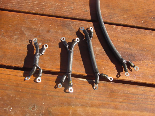
This is what the 4 jumpers look like. They have connector rings soldered on, and have recieved a few coats of rubber liquid sealer ("liquid tape") for weatherproofing. They later got a few coats of spray paint as well.
The main feedline attaches at the top wires (20m driven element) then is guided to the back (reflective element side) of the mast and runs down to the base. The balun winding ends up a few feet below the rotor, where there's an SO-239 connector for the main coax run.
