I recently picked up a nice Heil Pro-set headphone at a hamfest to use with my Kenwood. The Pro-set is the Pro-set 'ic' model, which uses a electret microphone element, and requires a DC voltage. This will not work with the Kenwood radio without additional power, so I wired up this adapter to make it work with the TS-850S and a foot pedal.
Fortunately, the Kenwood TS-850S has +8v on the microphone jack. I used this with a simple circuit built into a microphone adapter to match the headset. The result works well.
The circuit is based on one sent to me by Bob Heil.
I ended up using a 10uf tantalum capacitor because that's all I could find at Radio Shack that would fit inside the connector. The value isn't critical, as it's used to block the DC voltage from the microphone line while passing audio. A search on the web for "radio computer interface" or similar words will get you some variations. The capacitor part number was 272-1436. The 8 pin microphone connector is Radio Shack part number 274-025.
I also picked up a "Y" cable adapter with two mono 1/8" jacks to a stereo plug. I cut off the stereo plug, giving me two nicely made mono jacks with short wires. It's certainly possible to get the jacks and wire them yourself, but this saved some time and looks neater. The second mono jack is for a foot pedal and is wired to the PTT line and ground. With the headset and foot pedal, it gives me hands-free operation.
This circuit should be OK for computer headsets as well. In this case, you'll need a stereo jack instead of mono. Leave the ring unconnected, and feed the tip with the DC and capacitor while the base is ground. For computer headsets, you'll also need an adapter for the 1/8" stereo earphones to the 1/4" jack on the Kenwood.
I managed to squeeze the components so they would fit inside the microphone connector:
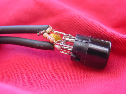
Be sure to slide on the connector shell and protective plastic sleeve before soldering anything. You'll also note some little ground braids at the base of the wires in the picture above - before closing up the connector, I clipped those off cleanly, and slipped little pieces of electrical tape between the pins and wires to prevent any shorts. I also wrapped a layer around the components and wires that weren't covered to stop it from touching the metal connector shell. It was a bit of a squeeze, but everything fit inside and I could close it up.
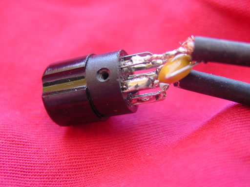
This is the view from the other side. My soldering isn't pretty, but it should work.
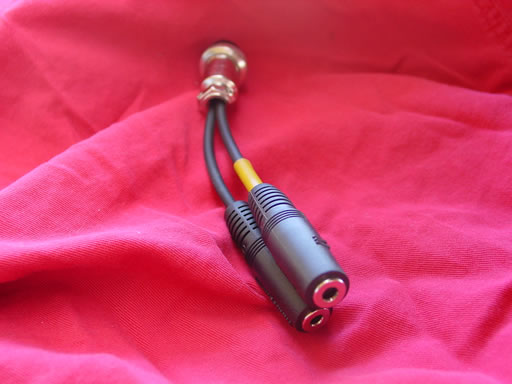
This is the final product. I put some yellow plastic tape on the PTT line and added some on the foot pedal cable so they are color-coded to match.
I hope this helps out. If you don't want to build something like this, take a look at the headsets and adapters sold by Bob Heil. I have no connection with the company, other than I like their products and am very thankful for the technical assitance.
If you have questions, you can contact me via email with my callsign at arrl.net
73,
- Dave
W6OT
Fine Print Disclaimer - this circuit worked well for me, but may not for your particular radio or headset. If you wire things wrong, you may damage your radio, headset and/or yourself. The author makes no guarantees about anything.