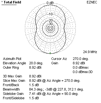
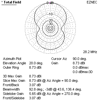
Azimuth Plots
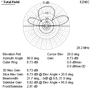
Elevation Plots
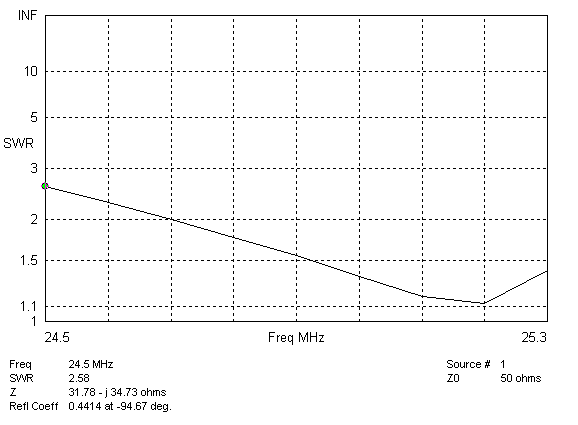
SWR Plots
20m
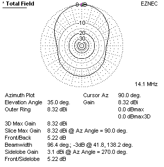
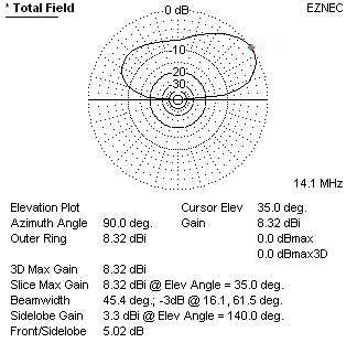
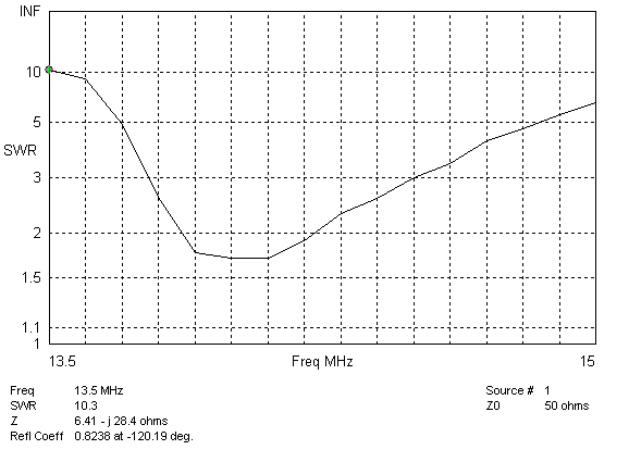
17m
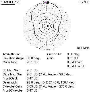
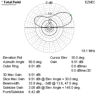
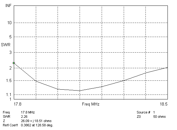
15m

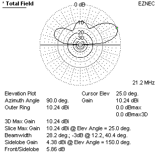
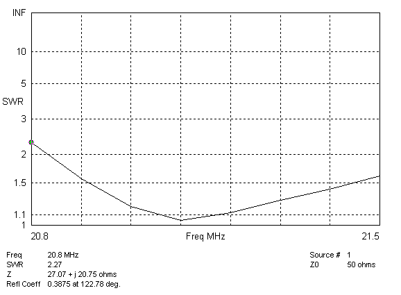
12m

10m
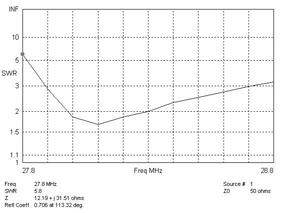
I worked a bit with EZNEC 4.0 to try and predict how the antenna would perform.
The results were mixed. Overall, the modelling seemed to work for individual bands, but EZNEC did not like the feedline between bands. If I put the current source at the top, the 10m curve would be way off. If it was put at the bottom, the 20m band wouldn't work. This seemed to contradict the way most people built their antennas, but actually fit what I found with mine.
I eventually gave up on this and worked on individual bands. I modeled all 5 bands worth of wires, but put the feed source at the band I was interested in. The other four band wires were in the model, but not connected to anything.
To build the model, I used an Excel spreadsheet to calculate all the wire endpoints and then imported it entirely into EZNEC. While I love EZNEC's antenna modeling, as a 3D modeling tool it's pretty rough. I found it easier to calculate everything in a spreadsheet rather than trying to shift, join, elongate wires inside EZNEC. The spreadsheet is available for download. It contains one macro which is used to write a CSV file to transfer the wires into EZNEC. You can also download the CSV files for each band below.
The plots look pretty good, except for 12m, which show the most problems. I had to add 2" to the original antenna length to get the SWR down to a good level, but the predicted pattern shows more gain towards the back than the front. This needs some experimentation to see if I can get this tweaked for a better shape.
Azimuth Plots |
Elevation Plots |
SWR Plots |
|
|---|---|---|---|
20m |
 |
 |
 |
17m |
 |
 |
 |
15m |
 |
 |
 |
12m |
Pattern predicted on 12m seems to have gain in the wrong direction.
|
 |
 |
10m |
 |
 |
 |